Home/GE/IS200BPIAG1AEB GE Input Module
IS200BPIAG1AEB GE Input Module
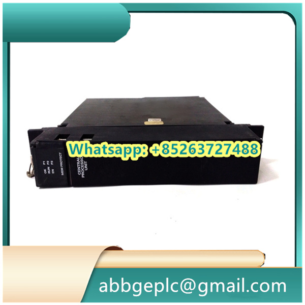
- Physical Condition: Visually inspect the 70-pin D-sub connector and terminal block for signs of damage, corrosion, or bent pins. Check that the adapter housing is intact with no cracks or deformation.
- Connection Integrity: Verify that the adapter is securely mounted to the equipment chassis or DIN rail. Ensure all locking screws (if present) are properly tightened to prevent vibration-induced loosening.
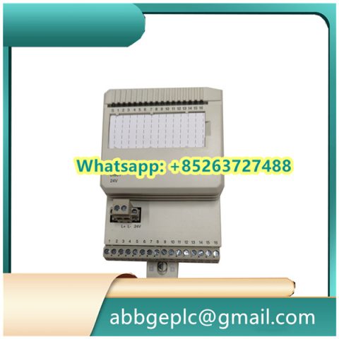
- Terminal Connections: Inspect wire terminations for tightness, ensuring no stray strands or loose connections. Confirm that wire gauge matches the terminal block specifications.
- Shielding Check: If applicable, verify that signal shielding is properly connected to the adapter’s grounding terminal to maintain noise immunity.
- Signal Integrity: Monitor associated I/O module indicators for abnormal status lights, which may indicate poor connection through the adapter.
- Temperature Check: Periodically feel the adapter surface during operation (when safe to do so) to detect unusual heating, which could indicate excessive contact resistance.
- Environmental Conditions: Ensure the adapter is operating within specified temperature and humidity ranges, away from direct moisture, dust accumulation, or chemical exposure.
- Cleaning: Use a dry, lint-free cloth to wipe dust from the adapter surface and connectors. For stubborn debris, use a soft-bristled brush on terminal block areas.
- Connection Verification: Recheck critical terminal connections for tightness, especially after equipment vibration or maintenance work on adjacent components.
- Visual Inspection: Look for new signs of wear, corrosion, or pin degradation that may have developed during operation.
- Documentation: Record any observations in the maintenance log, including unusual heating, connection issues, or physical damage requiring attention.
- Contact Cleaning: Use a proper electrical contact cleaner on D-sub connector pins and terminal block contacts (follow manufacturer guidelines).
- Torque Verification: Check and retighten mounting hardware and terminal screws to recommended torque specifications.
- Function Test: Perform a signal continuity test through the adapter to ensure unobstructed signal path between connected devices.

Product has been added to your cart

")
")
")
")

There are no reviews yet.