
")
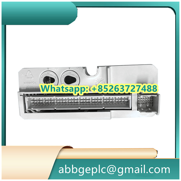
Debugging Steps for XS321A Pulse Counter Board
-
Initial Inspection
- Visually examine the board for any physical damage, loose connections, or solder defects
- Verify all components are properly seated, especially connectors and jumpers
- Check for any obvious signs of burnt components or electrolyte leakage
-
Power Supply Verification
- Connect the appropriate power supply according to the board specifications
- Measure the input voltage to ensure it matches the required parameters
- Verify that all voltage regulator outputs are within the specified range
- Check for any abnormal heat generation from power components
-
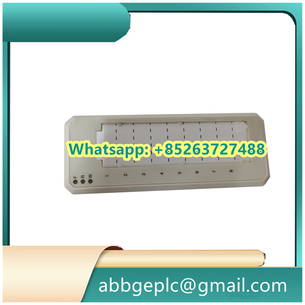
Connection Setup
- Ensure all interface cables are properly connected to their respective ports
- Verify the correct orientation of all connectors
- Confirm that the pulse input source is properly connected to the input terminals
- Check that any communication cables (if applicable) are securely attached
-
Basic Functionality Test
- Power on the board and any associated control system
- Verify that the status LED(s) illuminate as expected
- Check for any error codes or fault indicators
- Confirm that the board is recognized by the control system (if applicable)
-
Pulse Input Testing
- Connect a known good pulse generator to the input terminals
- Set the pulse generator to produce signals within the board’s specified range
- Monitor the board’s output or counters using appropriate test equipment
- Verify that the board correctly counts and processes the input pulses
-
Configuration Verification
- Check that all jumpers are set to the correct positions for your application
- Verify any DIP switch settings match the required configuration
- Confirm that software configuration parameters (if applicable) are set correctly
- Check for any firmware version requirements or compatibility issues


There are no reviews yet.