Home/PLC/UGTMEM-03LB2 Low-Voltage Motor Controller
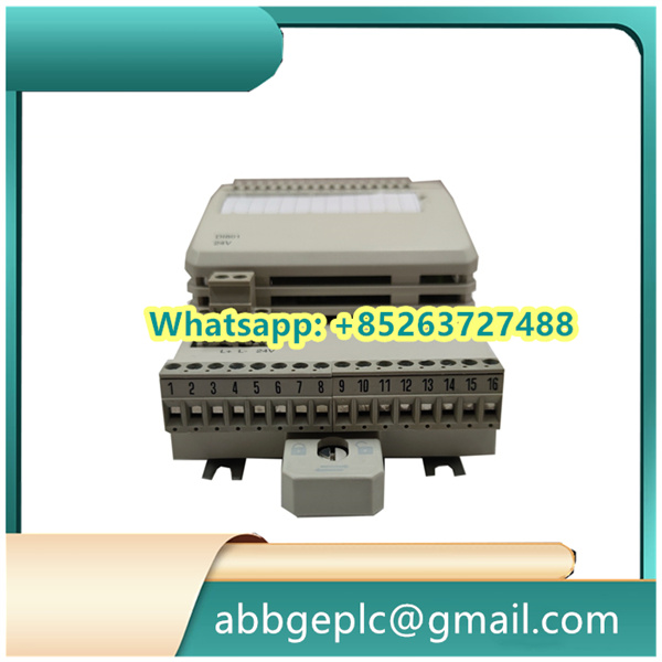
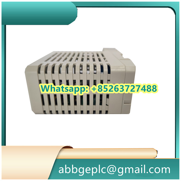
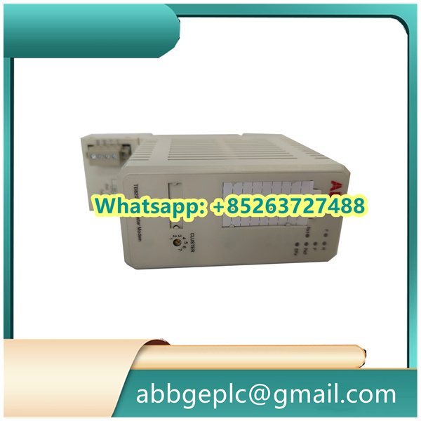
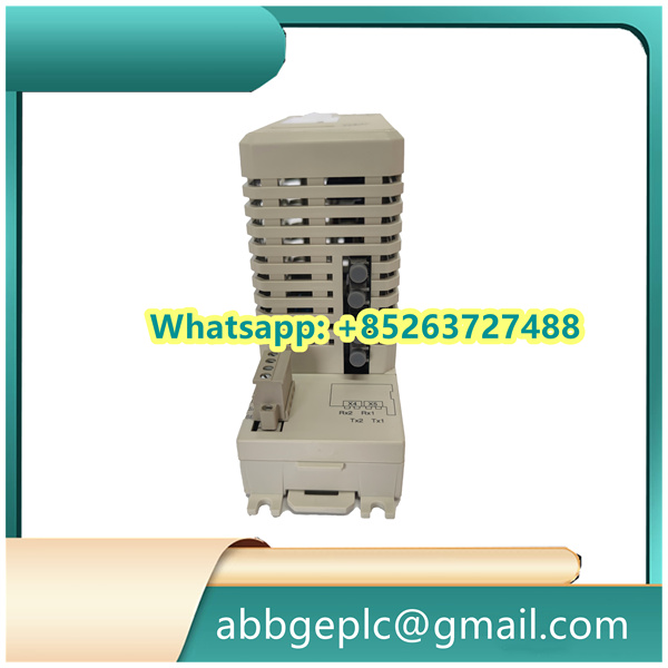
UGTMEM-03LB2 Low-Voltage Motor Controller
- Verify Compatibility: Confirm the modules compatible with the target system (e.g., ABB 800xA) and the designated I/O rack/slot per the system design documentation.
- Inspect the Module: Check for physical damage (e.g., bent pins, cracked casing, or loose components). Do not install if damage is detected—contact ABB support for replacement.
- Gather Tools & Materials: Prepare required items:
- Torque screwdriver (with compatible bits for module mounting screws).
- Anti-static wristband (to prevent electrostatic discharge damage).
- Cable ties and labeling tools (for wiring organization).
- Insulated tools (if working near live components).
- Safety Measures:
- Ensure the system power is completely disconnected (follow lockout/tagout, LOTO, procedures).
- Wear appropriate PPE: anti-static wristband, safety glasses, and insulated gloves.
- Work in a clean, dry environment to avoid dust or moisture ingress.
- Locate the Target Slot: Identify the designated slot in the I/O rack (refer to the system layout diagram). Ensure the slot is compatible with UFC719AE01 modules (check for matching connectors and mechanical alignment).
- Anti-Static Handling: Put on the anti-static wristband and connect it to a grounded surface (e.g., the I/O rack’s metal frame) to discharge static electricity.
- Insert the Module:
- Align the module’s guide rails with the slot’s rails in the I/O rack.
- Slide the module gently into the slot until it makes contact with the backplane connector.
- Apply even pressure to the front panel to fully seat the module (you may feel a slight click when properly connected).
- Secure the Module: Use the torque screwdriver to tighten the mounting screws on the front panel (typically 2 screws) to the specified torque (refer to ABB’s technical manual—usually 0.5–0.8 N·m). Do not over-tighten to avoid damaging the panel or threads.
- Review Wiring Diagrams: Refer to the UFC719AE01 3BHB003041R0001 wiring diagram (from ABB’s technical documentation) to identify terminal assignments for power, signals, and communication.
- Power Connections:
- Connect the power supply cable to the module’s power terminals (typically labeled “+24V” and “0V” for DC power). Ensure the voltage matches the module’s rating (check nameplate—usually 24 VDC ±10%).
- Tighten terminal screws to the specified torque (typically 0.3–0.5 N·m) to prevent loose connections.
- Signal & Communication Wiring:
- Connect field signals (e.g., analog inputs from sensors, digital outputs to actuators) to their respective terminals, following polarity markings (if applicable).
- Connect communication cables (e.g., for Ethernet or fieldbus) to the module’s communication ports (check for proper locking mechanisms, such as Ethernet RJ45 clips).
- Route cables neatly, avoiding sharp bends or contact with hot surfaces. Use cable ties to secure them to the rack’s cable management system.
- Grounding: Connect the module’s ground terminal (labeled “PE” or “GND”) to the system’s protective earth (PE) busbar using a dedicated ground wire (minimum 2.5 mm² cross-section). Ensure low-resistance connection (≤1 Ω).
Product has been added to your cart

")
")
")
")


There are no reviews yet.