
")
")
")
")
1. Pre-Operation Preparation & Safety Checks
Before powering on the module, confirm the following to avoid equipment damage or personal injury:
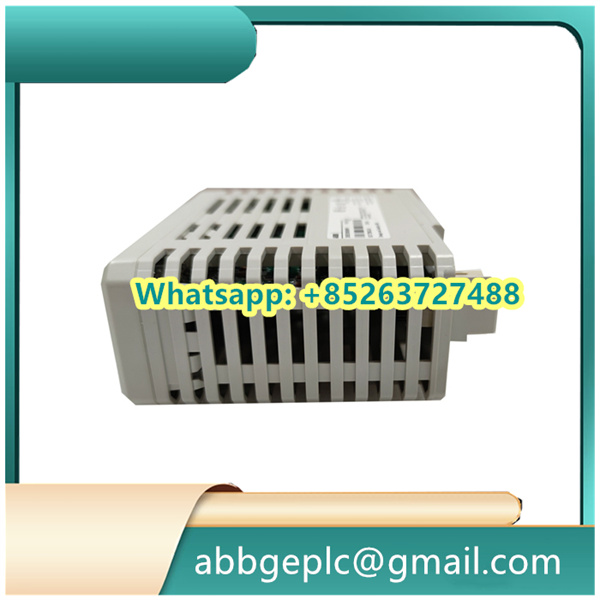
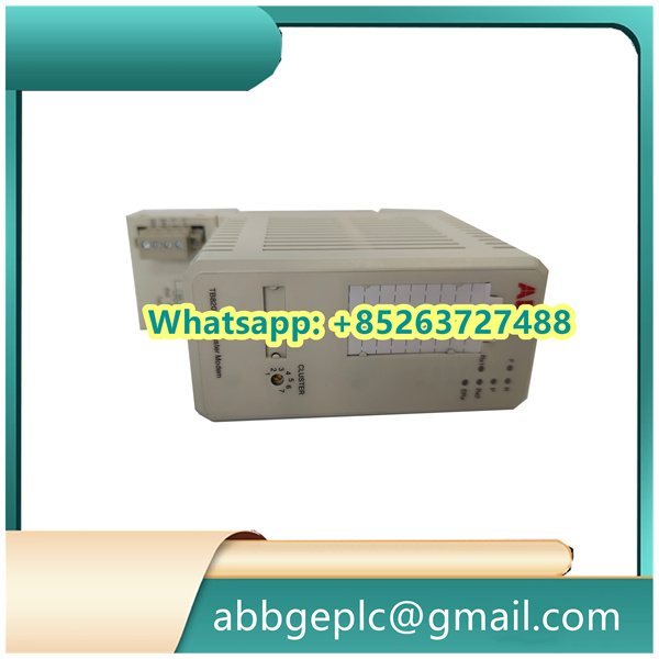
- Ensure the module model matches the system design and is correctly installed in the designated slot of the I/O rack.
- Verify that all wiring connections (power supply, signal cables, and ground wires) comply with it
Datasheet:- Power supply: Connect to the specified DC voltage (typically 24 VDC ±10%, check the module nameplate for exact values).
- Signal terminals: Ensure digital input (DI) lines are connected to field sensors (e.g., limit switches) and digital output (DO) lines to actuators (e.g., solenoid valves) without reverse polarity.
- Grounding: Confirm the module’s ground terminal is securely connected to the system’s protective ground (resistance ≤ 1 Ω).
- Inspect the module for physical damage (e.g., bent pins, cracked casing) or loose components. Do not power on if damage is detected.
- Wear appropriate PPE (Personal Protective Equipment) such as insulated gloves and safety glasses, especially when working with live circuits.
2. Startup Procedure
Follow this sequence to activate the module:
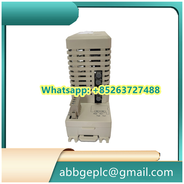
- Power On the I/O Rack: Turn on the main power switch of the I/O rack that houses the SS832 module. The module’s power indicator (labeled “PWR” on the front panel) will illuminate green if power is supplied correctly. A red “PWR” light indicates a power fault (check wiring or replace the power supply).
- System Initialization: Wait for the module to complete self-diagnosis (typically 30–60 seconds). The “STATUS” indicator will flash green during initialization and remain steady green once self-diagnosis passes. A flashing red “STATUS” light means a fault (refer to Section 5 for troubleshooting).
- Controller Communication Check: Log in to the ABB automation system’s HMI (Human-Machine Interface) or engineering software (e.g., Control Builder M). Navigate to the “I/O Module Status” menu and confirm the SS832 3BSC610068R1 is recognized as “Online” with no communication errors.
- Signal Calibration (If Required): For critical applications, use the engineering software to verify the module’s input/output accuracy. For digital inputs, simulate a signal (e.g., activate a field sensor) and confirm the HMI displays the correct “On/Off” status. For digital outputs, send a test command from the HMI and check if the connected actuator responds (e.g., a solenoid valve activates).
3. Normal Operation & Monitoring
During daily operation, monitor the module’s status and performance as follows:
- Real-Time Indicator Check: Periodically inspect the front-panel indicators:
- “PWR” (Green): Normal power supply; Red: Power failure.
- “STATUS” (Green): Normal operation; Red/Flashing Red: Fault.
- “DIx” (Digital Input Indicators): Green when the input signal is “On” (e.g., sensor triggered); Off when “Off”.
- “DOx” (Digital Output Indicators): Green when the output signal is “On” (e.g., actuator activated); Off when “Off”.
- HMI Status Monitoring: Use the automation system’s HMI to track:
- Module communication status (e.g., “Online/Offline”).
- Individual DI/DO channel status (to identify faulty field devices or wiring).
- Fault logs (e.g., overcurrent on DO channels, open circuits on DI lines).
- Load Check: Ensure the module operates within its rated load limits (max. current per DO channel: refer to the datasheet). Avoid overloading, as it may damage the module’s output circuits.
4. Shutdown Procedure
Shut down the SS832 module only when maintenance or system shutdown is required. Follow this order:
- Deactivate Field Devices: From the HMI, send a “Stop” command to all actuators connected to the SS832’s DO channels to ensure no active processes are interrupted.
- Disable Module in the System: In the engineering software, set the SS832 module to “Offline” mode to prevent unintended signal transmission during shutdown.
- Power Off the I/O Rack: Turn off the main power switch of the I/O rack. Confirm the module’s “PWR” and “STATUS” indicators are off.
- Lock Out/Tag Out (LOTO): Apply LOTO procedures to the I/O rack’s power source to prevent accidental power-on during maintenance.


There are no reviews yet.