Home/PLC/REF615C_D HCFKAEADAND2BAA1XD ABB protection and control
REF615C_D HCFKAEADAND2BAA1XD ABB protection and control
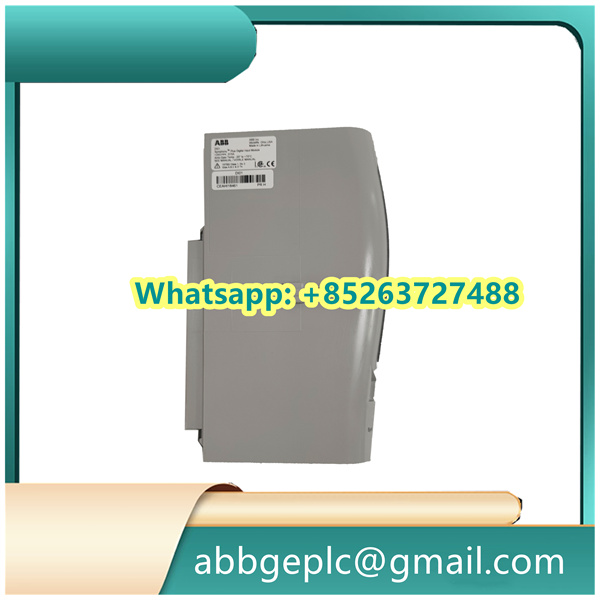
- Verify the product information: Confirm that the model number and hardware version of the controller match the design requirements and order specifications. Check for physical damage (e.g., cracks on the casing, loose pins) on the controller and its accessories.
- Prepare tools and materials: Gather essential tools including a torque screwdriver (with torque range matching ABB’s recommendations: typically 0.5–1.2 N·m for terminal screws), wire strippers, insulation testers, and anti-static wristbands. Prepare compatible accessories such as mounting rails (per ABB’s standard DIN rail specifications), terminal blocks, and shielded cables (if required for signal transmission).
- Safety confirmation: Ensure the main power supply of the target control cabinet is disconnected and locked out/tagged out (LOTO) to prevent accidental energization. Use an insulation tester to verify that the power terminals of the cabinet have no residual voltage (voltage should be 0 V).
- Select the installation position: Install the PM633 in a standard control cabinet that meets ABB’s environmental requirements (operating temperature: 0–60°C, relative humidity: 5–95% non-condensing, no direct sunlight or corrosive gases). Ensure there is a minimum clearance of 50 mm above and below the controller for heat dissipation (as specified in ABB’s technical datasheet).
- Mount to the DIN rail: Align the top mounting slot of the PM633 with the upper edge of the DIN rail (compatible with EN 60715 standard 35 mm DIN rails). Push the controller downward until it clicks into place. Gently pull the controller to confirm it is securely fastened to the rail (no looseness or wobble).
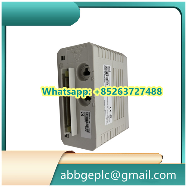
- Identify power terminals: Locate the power terminal block on the PM633 (marked “L” for AC live wire, “N” for AC neutral wire, and “PE” for protective earth wire on the controller’s label).
- Wire preparation: Strip the insulation of the power cables (recommended stripping length: 6–8 mm, as per ABB’s terminal specifications) and ensure no stray copper strands remain (to avoid short circuits).
- Terminal connection: Connect the AC live wire to the “L” terminal, the neutral wire to the “N” terminal, and the earth wire to the “PE” terminal. Tighten the terminal screws with a torque screwdriver to the specified torque (typically 0.8–1.0 N·m, refer to the PM633 technical manual for exact values). Pull each cable gently to confirm it is securely connected (no cable slippage).
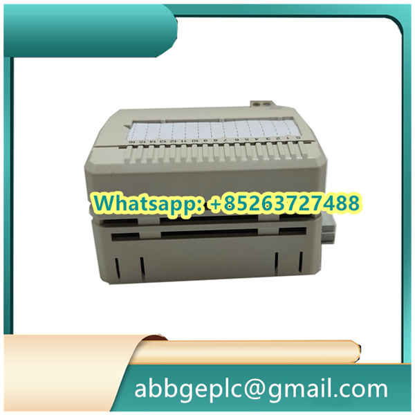
- Identify signal terminals: Refer to the PM633’s pinout diagram (provided in ABB’s user manual) to identify terminals for I/O signals (e.g., digital input “DI1”, analog output “AO1”) or communication ports (e.g., Ethernet, Profibus).
- Shielded cable handling (if applicable): For analog signals or high-speed communication signals, use shielded cables. Connect one end of the cable shield to the “GND” terminal of the PM633; the other end should be grounded at the signal source (per ABB’s grounding guidelines to avoid electromagnetic interference).
- Signal wire connection: Strip the insulation of the signal cables (stripping length: 4–6 mm) and connect them to the corresponding signal terminals. Tighten the screws to the specified torque (typically 0.5–0.8 N·m). Avoid crossing power cables and signal cables to minimize interference.
Product has been added to your cart

")
")
")


There are no reviews yet.