
")
")
")
")
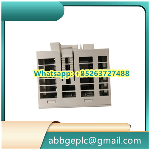
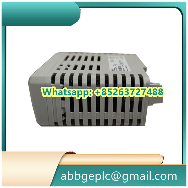
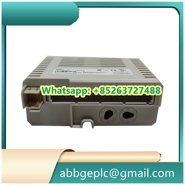
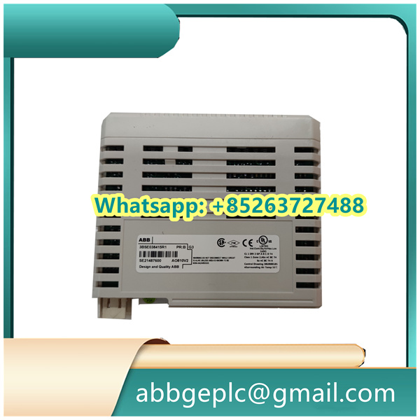
Operating Steps for DSQC328 ABB (Remote In/Out Expansion Unit)
The following steps are based on ABB’s standard installation and configuration guidelines for the DSQC328 ABB (a remote I/O expansion unit typically used in Advant OCS or industrial control systems):
1. Pre-Installation Preparation
- Confirm the DSDX451 module and its accessories (e.g., mounting screws, terminal blocks) are intact and match the order specifications.
- Power off the host control system (e.g., Advant OCS cabinet) to avoid electrical hazards during installation.
- Check the ambient environment: Ensure the operating temperature (0–60°C) and humidity (5–95% non-condensing) meet ABB’s requirements for the DSDX451.
2. Physical Installation
- Mount the DSDX451 module onto the standard DIN rail in the control cabinet, using the built-in rail clips. Align it with adjacent modules for proper airflow.
- Secure the module to the rail (if needed) with the provided screws to prevent vibration-induced displacement.
3. Wiring Connection
- Power Supply Wiring: Connect the 24V DC power cable to the “POWER IN” terminal block (labeled “+24V” and “GND”) on the DSDX451. Ensure polarity is correct to avoid module damage.
- I/O Signal Wiring:
- Connect digital input devices (e.g., sensors) to the “DI” terminals (20 channels total, 24V compatible) as per the wiring diagram in the DSDX451 manual.
- Connect digital output loads (e.g., relays) to the “DO” terminals (12 channels total, 0.1–3A current rating). Use appropriate fuses for high-current loads.
- Communication Wiring: Link the DSDX451 to the host control system via the “COMM” port (e.g., RS485 or proprietary ABB bus) using shielded cables. Ground the cable shield at one end to reduce electromagnetic interference.
4. Power-On and Initial Check
- Turn on the host control system and the DSDX451’s power supply. Verify the “POWER” LED on the module illuminates green (indicates normal power).
- Check the “STATUS” LED: A steady green light means the module is communicating with the host system; a red or flashing light indicates a communication error (recheck wiring or bus configuration).
5. Configuration via Host System
- Access the ABB control system software (e.g., Advant Master Configuration Tool) on the host computer.
- Add the DSDX451 to the system configuration: Select the module model (“DSDX451”) and assign it a unique address (to avoid conflicts with other remote I/O units).
- Configure I/O channels: Define the function of each DI/DO channel (e.g., “DI1 = Temperature Sensor Input,” “DO1 = Pump Control Output”) and set parameters like input delay or output overcurrent protection.
6. Function Testing
- Perform a manual test for digital inputs: Activate each connected input device (e.g., trigger a sensor) and confirm the corresponding “DI” LED on the DSDX451 lights up, and the host software displays the correct input state (e.g., “ON”).
- Perform a manual test for digital outputs: Send a “ON/OFF” command from the host software to each DO channel and verify the connected load operates as expected (e.g., relay activates/deactivates). Check the “DO” LEDs on the module for status confirmation.
- Conduct a system-level test: Run a sample control program to ensure the DSDX451 correctly transmits/receives signals to/from the host system, and all I/O functions work in line with the application logic.


There are no reviews yet.