
")


I t is a critical control module in GE’s industrial automation product lineup, typically used in power generation, heavy industry, and process control systems.
1. Pre-Installation Preparation & Safety Checks
1.1 Review Documentation: Familiarize yourself with the DS200DPCBG1A User Manual and the parent system’s (e.g., GE Mark VIe DCS) installation guide. Confirm the module’s compatibility with the system’s firmware version and backplane slot requirements.
1.2 Safety Isolation: Ensure the parent control cabinet’s main power switch is in the OFF position. Lock out/tag out (LOTO) the power source per site safety procedures to prevent accidental power-on during installation.
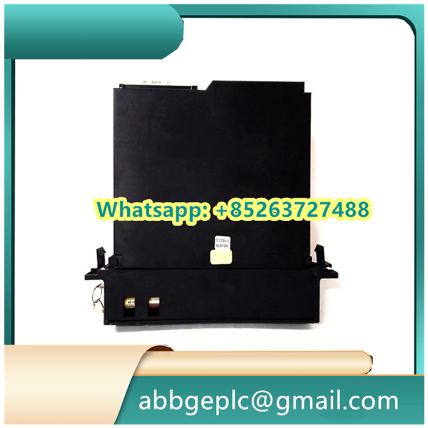
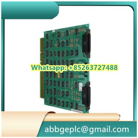
1.3 Module Inspection: Check the DS200DPCBG1A for physical damage (e.g., cracked housing, bent pins on the backplane connector, loose components). Verify that the module’s part number (DS200DPCBG1A) matches the replacement/installation requirement.
1.4 Tool & Material Preparation: Gather required tools (e.g., torque screwdriver, anti-static wristband, insulated wire strippers) and materials (e.g., compatible cables, cable ties, label markers). Wear an anti-static wristband throughout the process to protect the module from electrostatic discharge (ESD).
2. Backplane Slot Identification & Preparation
2.1 Locate the Target Slot: Identify the correct backplane slot in the control cabinet—refer to the system’s slot mapping diagram (typically provided in the cabinet’s wiring manual). The DS200DPCBG1A is designed for specific backplane interfaces (e.g., GE’s common backplane for DS200 series modules); do not install it in an incompatible slot.
2.2 Clean the Slot: Use a dry, lint-free cloth to wipe the backplane connector in the target slot, removing dust, debris, or oxidation. Avoid using alcohol or corrosive cleaners, as they may damage the connector pins.
2.3 Check Backplane Power: Use a multimeter to confirm that the backplane slot has no residual voltage (target: 0 V DC/AC) before inserting the module. This prevents short circuits or component damage during installation.
3. Module Installation into the Backplane
3.1 Align the Module: Hold the DS200DPCBG1A by its top and bottom edges (avoid touching the circuit board or connectors). Align the module’s backplane connector with the slot’s connector, ensuring the module is parallel to the cabinet’s guide rails.
3.2 Insert the Module: Gently push the module into the slot until you feel a slight “click”—this indicates the backplane connector is fully mated. Do not apply excessive force, as this may bend or break the connector pins.
3.3 Secure the Module: Use the torque screwdriver to fasten the module’s front-panel screws to the cabinet’s mounting rail. Follow GE’s recommended torque value (typically 0.8–1.2 N·m) to ensure a secure fit without damaging the module’s housing.
4. Wiring Connection
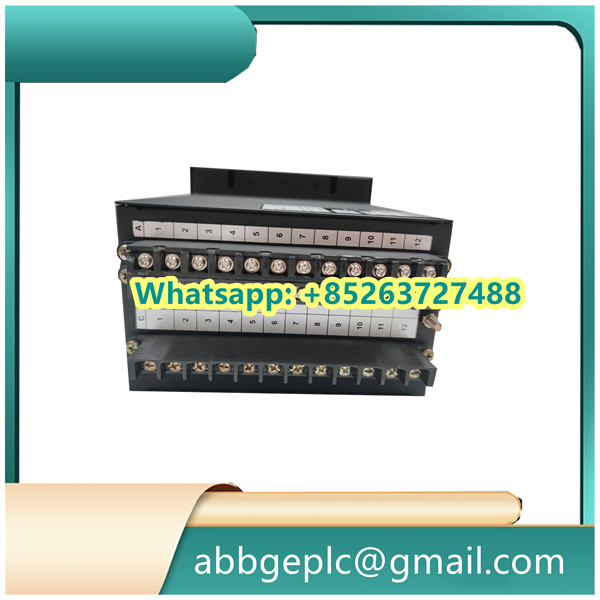
4.1 Refer to Wiring Diagram: Use the DS200DPCBG1A’s wiring diagram (included in the user manual) to identify the function of each terminal (e.g., power input, signal input/output, communication ports). Label cables in advance to avoid miswiring.
4.2 Power Wiring: Connect the module’s power cables to the designated terminals (typically 24 V DC or 125 V DC, per system requirements). Ensure correct polarity (positive/negative) to prevent reverse-voltage damage. Tighten terminal screws with a torque of 0.5–0.7 N·m to avoid loose connections.
4.3 Signal & Communication Wiring:
- For analog/digital signal cables (e.g., from sensors or actuators), use shielded twisted-pair cables to minimize electromagnetic interference (EMI). Ground the shield layer at the cabinet end (single-point grounding) per GE’s EMC guidelines.
- For communication ports (e.g., RS-485, Ethernet, if applicable), connect the cables to the corresponding terminals, ensuring compliance with protocols (e.g., Modbus RTU for RS-485). Verify that the cable length does not exceed the protocol’s maximum distance (e.g., 1200 m for RS-485).
4.4 Secure Cables: Use cable ties to organize the wiring, keeping cables away from high-voltage components (e.g., 480 V AC power cables) to avoid crosstalk. Maintain a minimum distance of 30 cm between signal cables and power cables, as specified in GE’s wiring standards.
There are no reviews yet.