

")
")
I. Pre-Debugging Preparation
1. Hardware Inspection
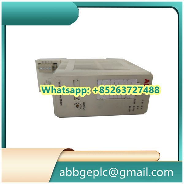
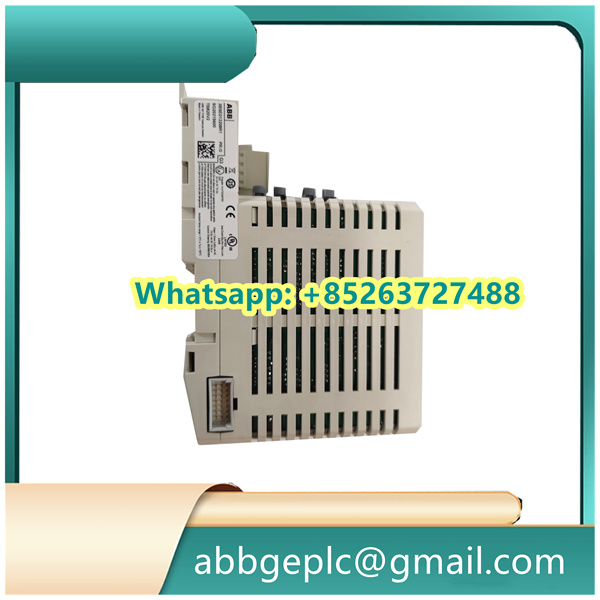
- Verify that the DI651 module model (e.g., 3BSE022369R1) matches the system configuration. Check for no physical damage to the module and no bent pins.
- Ensure the module is securely installed, the backplane connector (e.g., TB651 terminal board) is fully seated, and all screws are tightened.
- Confirm correct external wiring: Input signals (typically dry contacts or DC 24V level signals) are connected to the corresponding channel terminals, common terminals (COM) are wired according to polarity, and shielding layers are grounded at one end.
2. Tool and Software Preparation
- Install the ABB programming software Control Builder M (for configuring module parameters).
- Prepare the engineering file of the 800xA System (or AC800M controller) and ensure the DI651 has been added to the hardware configuration.
- Prepare tools such as a multimeter (for measuring input signal voltage), screwdrivers, and insulating gloves.
II. Hardware Connection and Power Supply Check
1. Power Supply Test
- Power on the AC800M controller and I/O rack, then check the status of the DI651 module indicators:
- The Power LED (PWR) should be steadily on (green). If not, inspect the rack power supply or check for module faults.
- The Fault LED (FAIL) should be off when there is no fault; if it flashes or stays on, troubleshoot communication or hardware issues.
2. Input Signal Line Test
- Disconnect the module from external devices, use a multimeter to measure the signal voltage at the input terminals (e.g., it should be DC 24V when the external device is activated and 0V when deactivated) to confirm the external signal source is normal.
- Check for short circuits, open circuits, or grounding faults in the wiring.
III. Software Configuration and Parameter Check (via Control Builder M)
1. Module Configuration Confirmation
- Open the Control Builder M project, navigate to “Hardware Configuration,” and locate the I/O rack where the DI651 module is installed.
- Verify that the module address matches the physical DIP switch settings (if applicable); the default setting is usually auto-assignment (recognized by the controller).
- Check the signal type configuration of the module: The DI651 supports dry contacts (passive) or wet contacts (active DC 24V). Select the correct input mode (e.g., “DI_24V”) based on actual wiring.
2. Channel Parameter Setting
- Configure the following parameters for each input channel (as required):
- Filter Time: The default value is typically 10ms; adjust it according to on-site interference (e.g., extend to 50ms for anti-interference).
- Signal Inversion (Invert): Enable or disable logical inversion of the input signal (e.g., “1” indicates open, “0” indicates closed).
- After configuration, download the project to the AC800M controller and restart the I/O rack where the module is located.
IV. Signal Testing and Function Verification
1. Online Signal Monitoring
- In the 800xA operation interface or the “Online” mode of Control Builder M, locate the input channel variables of the DI651 module (usually named DI651_ChX, where X is the channel number).
- Manually trigger external devices (e.g., close/open switches, activate sensors) and observe if the channel status changes in real time:
- When the signal is on, the variable value should display “1” (or “TRUE”), and the corresponding module channel indicator (if available) should light up.
- When the signal is off, the variable value should display “0” (or “FALSE”), and the indicator should turn off.
2. Fault Simulation and Diagnosis
- Intentionally disconnect the wiring of a specific channel and check if the system can correctly detect “signal loss” (an alarm may be triggered under certain configurations).
- If the signal is abnormal, use the “Event Log” in 800xA or module diagnostic information to check for prompts such as “channel fault” or “communication interruption” and locate the problem.
V. Post-Debugging Confirmation
1. Stability Test
- Allow all input signals to operate under normal working conditions for a period (e.g., 30 minutes) and observe if the signals remain stable without false alarms or loss.
- Check that the module temperature is normal (no overheating) and that heat dissipation is effective.
2. Documentation Recording
- Record the module’s hardware address, channel configuration parameters, wiring diagram, and test results for future reference.
Common Troubleshooting
- If a specific channel has no signal response: Check the wiring and external signal source, or try replacing the channel for testing (to rule out module channel faults).
- If all channels have no signal: Inspect the module power supply and backplane communication, or re-download the configuration file.
- If the signal fluctuates frequently: Increase the filter time or check if the external wiring is subject to electromagnetic interference (enhance shielding if necessary).


There are no reviews yet.