
")

")
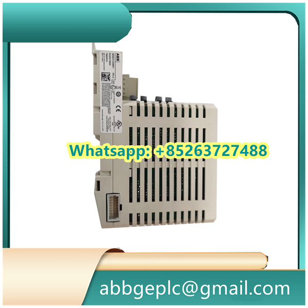
Operation Steps for CI854A-EA 3BSE030221R2
- Pre-Operation Preparation
- Environmental Check: Ensure the installation area meets the device requirements: temperature range of 0°C to 60°C, relative humidity of 5% to 95% (non-condensing), and away from strong electromagnetic interference sources (such as large motors, high-voltage lines) and corrosive gases.
- Equipment Inspection: After unpacking, check the CI854A-EA module for physical damage (e.g., cracks in the casing, bent pins). Verify that accompanying accessories (mounting screws, connection cables, etc.) are complete.
- Tool and Documentation Preparation: Prepare tools such as screwdrivers, insulated gloves, and a multimeter. Have the device manual, system wiring diagrams, and configuration guides on hand. Ensure operators are familiar with the module’s basic principles and safety precautions.
-
- Module Installation
- Power Off Operation: Confirm that the associated control system is powered off. Implement the Lockout-Tagout (LOTO) procedure to prevent accidental power-on, which could damage the device or cause electric shock.
- Mounting: Align the CI854A-EA module with the standard DIN rail in the control cabinet. Slide the module onto the rail until the locking clips engage securely. Use the provided screws to fasten the module’s side panels to prevent loosening due to vibration.
- Wiring Connections:
- Power Supply: Connect the 24V DC power cable to the designated terminals (marked “+24V” and “0V”), ensuring correct polarity. Tighten the terminal screws to a torque of 0.5–0.6 N·m to avoid poor contact.
- Communication Cables: Connect Profibus DP or other communication cables to the corresponding ports (e.g., DP IN/OUT). Use shielded twisted-pair cables, and terminate the shield at a single point with a grounding resistance of less than 4Ω to reduce electromagnetic interference.
- System Configuration
- Power-On Initialization: Restore power to the system. Check that the module’s power indicator (PWR) illuminates green steadily. If it flashes or remains off, verify the power supply and wiring.
- Software Connection: Launch the configuration software (e.g., ABB Control Builder M). Establish a connection to the CI854A-EA module via the network or local interface using its default device address (refer to the manual).
- Parameter Setting: Configure communication parameters (baud rate, parity, address) and functional parameters (data transmission mode, diagnostic settings) according to the system requirements. Save the configuration and download it to the module. Wait for the settings to take effect (typically 1–2 minutes).
-


There are no reviews yet.