
")
")
")
")
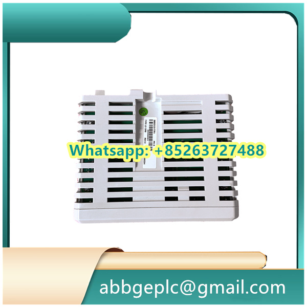
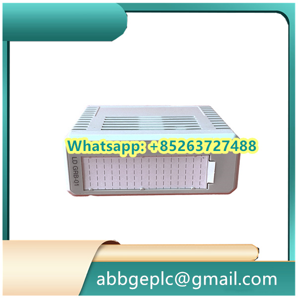
Operation Steps for CI801 3BSE022366R1 ABB (Communication Interface Module)
- Pre-Installation Preparation
- Ensure the industrial control cabinet is powered off and isolated from the main power supply to prevent electrical hazards.
- Verify that the module (CI541V1 3BSE014666R1) is compatible with the target control system (e.g., ABB AC 800M or similar DCS/PLC architectures) by checking the system compatibility matrix.
- Inspect the module for physical damage, such as bent pins or cracks, and confirm all included accessories (e.g., mounting screws, connector plugs) are present.
- Mechanical Installation
- Locate the designated slot in the control rack or backplane, aligning the module’s guide rails with the rack’s mounting rails.
- Slide the module into the slot until it makes firm contact with the backplane connector. Secure it using the captive screws on the front panel, tightening to the recommended torque (typically 0.5–0.8 N·m) to ensure proper electrical connectivity.
- Wiring and Connection
- Refer to the module’s wiring diagram to identify the communication ports (e.g., Ethernet, fieldbus, or serial interfaces) and power terminals.
- Connect the communication cables (e.g., Cat5e/Cat6 for Ethernet, shielded twisted-pair for fieldbuses) to the corresponding ports, ensuring proper shielding and strain relief to minimize electromagnetic interference.
- If applicable, connect the auxiliary power supply (e.g., DC 24V) to the designated terminals, verifying polarity to avoid damage.
- Power-Up and Initialization
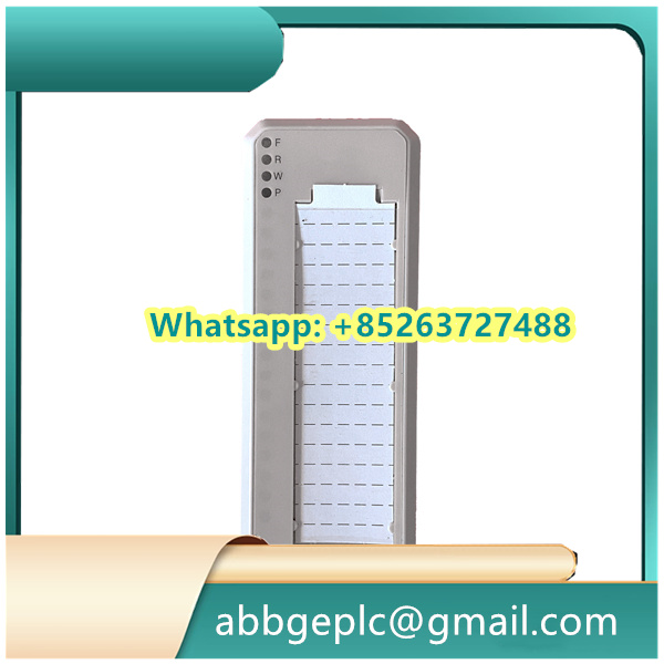
- Restore power to the control cabinet and power on the system. The module’s status LED should illuminate (e.g., green for normal operation; red or flashing for faults).
- Allow the module to initialize, which may take 1–2 minutes. During this period, the LED may flash intermittently before stabilizing.
- Configuration via Engineering Software
- Launch the compatible engineering tool (e.g., ABB Control Builder M) and establish a connection to the control system.
- Locate the CI541V1 module in the hardware configuration tree and assign it a unique device name or address (e.g., IP address for Ethernet-based communication).
- Configure communication parameters, such as protocol type (e.g., Profinet, Modbus TCP), baud rate, and data exchange intervals, based on system requirements. Save the configuration to the module.
- Functional Testing
- Perform a communication test by sending a diagnostic command from the engineering tool to verify data transmission between the module and the controller.
- Monitor real-time status via the tool’s dashboard, checking for errors (e.g., “no communication” or “protocol mismatch”) and troubleshooting by rechecking wiring or reconfiguring parameters if necessary.
- Validate interoperability with connected devices (e.g., sensors, actuators, or other controllers) by triggering test signals and confirming data reception/transmission logs.
- Commissioning and Documentation
- Once functionality is confirmed, lock the module’s front panel (if equipped) to prevent unauthorized access.
- Update the system documentation to include the module’s location, configuration settings, and wiring details for future maintenance.
- Conduct a final inspection to ensure all connections are secure, cables are neatly routed, and the module operates without faults under normal load conditions.


There are no reviews yet.