
")
")
")
")
Installation & Operation Guide
1. Pre-Installation Preparation
- Environmental Check
Verify ambient temperature (0-55°C) and humidity (<95% non-condensing). Ensure ESD protection by wearing grounded wrist straps. - Hardware Inspection
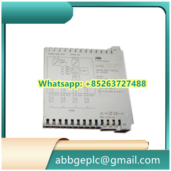
Examine PCB for physical damage (e.g., cracked components/bent pins). Confirm module label matches “3HAC12924-1” with firmware version ≥V2.1.
2. Hardware Integration
- Mounting
- Align with DIN rail slot (EN 60715 standard) and lock with snap-on mechanism.
- Torque terminal screws to 0.6Nm±10% (Phoenix-type connectors).
- Wiring
- Power Supply: Connect 24VDC (±10%) to
V+/V-terminals, observing polarity. - Signal Lines:
- Shielded twisted-pair for PROFIBUS-DP (terminate with 220Ω resistor at bus ends).
- Isolate analog I/O cables from power lines (>200mm spacing).
- Power Supply: Connect 24VDC (±10%) to
3. Power-Up Sequence
- Initialization
- Apply power while monitoring
STATUS LED:- Solid green: Normal operation
- Red blinking: Fault detected (refer to §4.2)
- Apply power while monitoring
- Communication Setup
- Set node address via DIP switches (SW1-1 to SW1-8 for binary encoding).
- Baud rate configurable through GSD file (default: 1.5Mbps).
4. Functional Verification
TEST PROCEDURE: 1. Inject test signal (e.g., 4-20mA) to AI1, verify output on AO1 (±1% accuracy). 2. Trigger digital input DI1, confirm relay output DO1 activation (delay <10ms). 3. Monitor PROFIBUS cyclic data exchange with master (timeout tolerance: 2x Tslot).
5. Maintenance & Troubleshooting
- Routine Check
Clean ventilation slots quarterly using dry compressed air (≤0.3MPa). - Error Codes
Code Meaning Action E02 Overvoltage Check PSU output ≤26.4VDC E05 Communication timeout Verify termination resistors


There are no reviews yet.