
")
")
")
1. Safety Precautions
Before operating or maintaining the 07ZE23 GJR2292800R202 unit, strictly adhere to the following safety requirements to prevent personal injury, equipment damage, or system malfunctions:
- Ensure all operators have received formal training on ABB low-voltage control components and understand the unit’s technical specifications (refer to the Product Datasheet 3BHL000XXXXX for details).
- Wear appropriate Personal Protective Equipment (PPE), including insulated gloves, safety glasses, and anti-static wristbands, to avoid electrostatic discharge (ESD) or electrical shock.
- Verify that the upstream power supply of the unit is completely disconnected (lockout/tagout, LOTO) before installing, removing, or wiring the component.
- Do not operate the unit in environments exceeding the rated conditions: operating temperature -25°C to +60°C, relative humidity ≤95% (non-condensing), and altitude ≤2000m.
- Avoid direct contact with exposed terminals or components when the unit is powered on; check for abnormal heat, sparks, or unusual noises during operation.
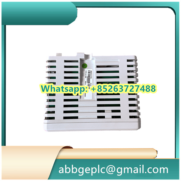
2. Component Overview
The 07ZE23 GJR2292800R202 is an ABB auxiliary control module designed for low-voltage power distribution systems, typically used to monitor and switch auxiliary circuits (e.g., fan control, lighting, or auxiliary power supplies). Key components and indicators are identified as follows:
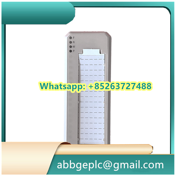
| Component/Indicator | Location | Function Description |
|---|---|---|
| Power Input Terminals (L/N) | Top of the module | Connect to AC 220V/380V (check nameplate for exact voltage) |
| Signal Input Ports (IN1~IN4) | Front panel, left side | Accept dry contact or analog signals (0~10V DC) for status monitoring |
| Relay Output Ports (OUT1~OUT2) | Front panel, right side | Provide NO (Normally Open) contacts for load control (max current: 5A/250V AC) |
| Status LED (PWR) | Front panel, center | – Green: Power supply is normal – Off: No power or internal power failure |
| Status LED (RUN) | Front panel, center | – Steady green: Module is operating normally – Blinking red: Fault detected (e.g., overcurrent, signal loss) |
| Reset Button (RST) | Front panel, bottom | Manual reset after fault clearance (press and hold for 2 seconds) |


There are no reviews yet.